 Ultralight
Aviation
Ultralight news, Ultralight
Classified
Ultralight
Aviation
Ultralight news, Ultralight
Classified
Lazair technical bulletins http://lazair.com
| Volume 1 | Volume 2 | Volume 3 | Volume 4 | Volume 5 | Volume 6 | Volume 7 | Volume 8 |
Rotax 185 Aircraft Engine Advisory's as taken from Reg's Newsletters (Reg's aircooled engine center)
Newsletter 1 Newsletter 2 Newsletter 3 Newsletter 4 Newsletter 5 Newsletter 6 Newsletter 7
1.1 RUDDERVATOR HINGE BOLT
The 47 bolt that fits into the P1 at the root end of the ruddervator should be held in by bottoming the bolt thread in the threaded hole and should not tighten on the B4. This is to ensure that the bolt has no tendency to unscrew. If your bolt is tightening on the B4, then either replace the bolt with a longer bolt or safety wire the head of the bolt.
1.2 NYLON BEARINGS
Wherever there is a B3, B4 or B6 other than the B4 mentioned in number 1 above, the situation should be such that when the moveable surface is moved the bolt holding the bearing (B3, B4 or B6) should remain stationary. If this is not the case, remove the bearing and file the hole bigger in the moveable surface so that the bolt can then be further tightened without the bearing seizing to the moveable surface.
1.3 FUEL LINE CONNECTIONS
As mentioned in the flying manual, all gas line connections should be safety wired before flying to prevent air bubbles in the gas line (this includes where the gas line attaches to the engine).
1.4 MAINTAIN AIRSPEED
There have been an increasing number of incidents where pilots have tried to climb out at too low an airspeed which results in a mush condition where the aircraft will no longer climb and possibly descend. The mush is controllable, yet sometimes the nose will drop as in a stall. The danger is that people don't recognize this condition, especially when trying to go over obstacles. With this emphasis we hope to prevent some bent tubes and wings.
1.5 IN-FLIGHT RESTARTS
We would like to remind people that air restarts are tricky and should only be attempted at altitudes over 1000 feet until a significant skill is obtained in doing this manoeuvre.
1.6 PRIMER BULBS
We have received word from a few customers that primer bulbs have been failing due to a reaction with the gasoline. Inspect your primer bulbs frequently and if you see any signs of deterioration, replace the bulb with one obtained locally.
1.7 PREFLIGHT INSPECTIONS
Lastly, we would like to remind you of the obvious need to do a complete and thorough preflight inspection before you fly.
2.1 Water on wings:
Water on the wings of any airplane, whether caused by dew or rain1 can add a considerable amount of weight and therefore will alter the flight characteristics - especially the rate-of-climb. If you're flying the Lazair, the effect of water on the wings is much more noticeable than it would be with a more conventional light airplane.
The leading edge of the Lazair wing is very smooth and relatively free of rivets. This, along with the super-smooth mylar covering makes the Lazair wing one of the most aerodynamically clean wings ever used on a sub-sonic airplane, and is one of the reasons a Lazair is able to outperform most microlights which have more than twice the power-to-weight ratio.
However, with beads of water on the wing (and especially on the leading edge) much of the smoothness of the wing is destroyed and climb performance will be significantly reduced.
A take-off roll three to four times as long is not uncommon if the wings are wet. You may also find that immediately after lift-off, the airplane will assume a mush attitude and refuse to climb until It reaches an airspeed of about twenty-five or thirty miles per hour and the water beads begin to disperse.
2.2 LONG GRASS
Taking off or landing in reasonably long grass (up to a foot high) is generally not a problem except for the obvious increase in the take-off roll. However, the real long stuff (one and a half to two feet) can get caught In the cables (you know - the ones' people keep walking into) and can put enough stress on the tail to bend T 11 (the spreader) or even break F4 (the rear stabilizer attach fitting).
This is not a common occurrence but it has happened a couple of times and you should be aware of it. Any time you land in long grass (whether intentionally or otherwise) check your T 11 and F4 before you take off again.
2.3 PRIMER BULBS
We have recently discovered that the major cause of those annoying air bubbles in the fuel line Is the primer bulb. If you're having this problem, the best way to get rid of it is to get rid of the primer bulb. This obviously makes it more difficult to get fuel to the engines Initially, but it should solve the bubble problem.
If you want to retain the primer, be sure it is positioned so that the outlet end of the primer is lower than the inlet end. This will reduce the possibility of trapped air in the primer entering the fuel line to the engine.
2.4 SPARK PLUGS
Relative to the engines used on most other microlights, the engines on the Lazair have demonstrated excellent reliability. However, like any other two-stroke engine, they will refuse to run with fouled spark plugs. If an engine quits due to fuel starvation, it will usually cough and sputter a few times before It stops.
If you notice an engine stop very suddenly with no warning, there's a high probability that the problem Is due to a fouled plug. A small fiber of electrically conductive carbon, so small you can barely see It, can cause an engine to stop.
Although no one can guarantee you'll never have a fouled plug problem, there are several things you can do to reduce the possibility to a minimum.
(a) do not use unleaded fuel.
(b) Use a good quality two-stroke oil in the gasoline. Although~ there are, no d6ubt, many good oils available, the one we recommend is Granberg (eutetic), mixed in a ratio of 100 to 1.
(c) Check and clean (if necessary) you plugs regularly. Once every five hours is recommended, but this can be altered, based on your own experience. Plugs may be cleaned with a wire brush or with a small sandblaster of the type available at most automotive accessory stores and catalogue outlets for about ten dollars. If you use one of these units, be sure you clean all the sand particles out of the plug before you re-install it. Regardless of how you clean your plugs, make certain you clean all the grit out of the threads and apply a bit of oil before you screw it Into the head. Aluminum heads can be damaged very easily by an improperly Inserted spark plug. An easy way to avoid wasting valuable flying time cleaning plugs is to keep one or two spare sets of plugs and rotate them periodically.
(d) Never turn the engine over with the spark plug lead off the spark plug, or with the spark plug incorrectly grounded as this could destroy your Ignition module. This is a very costly mistake.
2.5 STRUT PLUG HOLE LOCATION
Make sure that the 1/4" holes in the lower strut plugs are drilled with the center of the hole at least 1/2" from the end. If they are not contact Ultraflight or your local dealer.
3.1 ROUTING OF MAGNETO WIRE
When you mount your engines and connect the magneto grounding wire (the one which runs back to the kill switch) make sure the wire is routed well away from the cylinder head. If it rests against the head, the insulation could melt. causing the wire to be grounded, and stop the engine.
3.2 ERROR IN AIRSPEED INDICATOR READING
If you read your copy of "Learning to Fly the Lazair" you're probably aware that the Hall Brothers airspeed indicator, when mounted on the fuselage of the Lazair, provides a good relative indication of airspeed, but does not give an accurate reading in miles per hour. At take-off speed, the reading Is probably accurate within two or three miles per hour but at higher speeds, your actual airspeed will be much higher than Indicated. With a reading of 40 mph, your actual airspeed will be probably about 55 mph, and this Is the recommended maximum flying speed.
3.3 LEAKY FUEL FILTERS
As reported in a previous letter, most of the problems of air bubbles~in the fuel lines have been traced to the primer bulb. However, we have had a couple reports of leaks in the fuel filter. To eliminate this potential problem, we recommend that the in-line filter be replaced with the submersible type.
3.4 AILERON PLUGS
One of our high time demonstrator aircraft has recently developed loose rivets in the aileron plug P4. This particular aileron had only four rivets in it rather than eight as specified in the assembly instructions, so we do not anticipate a problem on customer-built aircraft, but we do suggest that you check your aileron plugs occasionally during the walk-around.
3.5 DON'T DO IT IN THE ROCKS
Although the tail of the Lazair has been designed to withstand the loads imposed by nommal and very heavy landings it is not indestructible We have had a report of one aircraft which was taking off from a rock-strewn field and struck the tall on a large rock at high speed just prior to take-off. The impact was sufficient to bend the rear stabilizer tube T1O and dislodge the outboard ruddervator hinge pin. Although the pilot was able to maintain control and land without incident, this situation should obviously be avoided if possible. If you have to take off from a rocky field, remember to keep the tall off the ground.
3.6 CHECK YOUR TAIL
In the last letter we mentioned the possibility of breaking the rear tail attach fitting (F4) by landing In very tall grass. Since it might be possible to break or crack an F4 without being aware of It, we suggest that you include a check of the F4 in your walk-around. The most probable location for a crack, if one should ever occur, is through the rivet hole. so this area should be checked carefully.
3.7 TIRE PRESSURE
If you're lucky enough to have the new tundra wheels, remember that they are designed for Low Pressure tires. The best tire pressure will depend on the type of field and the weight of the pilot, but should not under any circumstances, exceed 18 PSI.
3.8 BLUE MAGNETOS
A few of the engines shipped in the past couple of months have had magneto Ignition units with a light blue housing. For some reason, these engines will not always run properly with the two magnetos' connected to a common grounding switch. (We suspect that the older units contained a decoupling diode which has not been installed In the new blue ones, but this not yet been confirmed by the manufacturer). In any case, the problem can be eliminated by using a separate switch for each engine (or by using a double pole switch). To save time, if you have the blue magneto units, we suggest that you obtain another switch locally, but if you can't locate one, let us know and we'll send you one.
3.9 AEROBATICS
We have heard recently that a few customers have been flying loops and other aerobatic maneuvers In their Lazairs. While there is no doubt that the Lazair Is capable of executing some of these maneuvers (as demon strated by the Ultraflight factory test pilots), this type of flying is definitely ~not recommended for the average Lazair pilot. The Lazair is stressed for 4 g's positive and 2 g's negative. This is quite adequate for any normal flying conditions but it is not even close to the stress requirements for fully aerobatic airplanes.
A properly executed inside loop will probably pull less than 3 g's. However, a poorly executed loop (one entered at too high an airspeed or with an abrupt movement on the cont?ol column or one with a prolonged period of vertically downward flight) could pull well In excess of the 4 g design limit for the aircraft. We don't want to hear about someone pulling the wings off in flighti Accidents of this type are very easyto avoid - just don't do it.
3.10 IN-FLIGHT RESTARTS
One of the attractive features of the Lazair is its ability to soar with the engines off, and then fly home with its engines restarted. However, restarting these engines in flight is a technique to be practised and learned only after the basic skills of flying the Lazair have been mastered. As was suggested in the first of these update letters, your first attempt to restart in flight should be made at an altitude of at least 1000 feet. It should also be made In an area where you can glide to a safe landing should your restart be unsuccessful.
Although a restart looks easy when you're on the ground watching someone else do it, you may find it's a bit different when you're up In the air trying it yourself. First of all, it's necessary to lean forward to grasp the pull cord - this can be a difficult reach for a short-armed pilot. Leaning forward will change the trim and put the aircraft into a nose down attitude. This can be compensated for by a slight back pressure on the stick, but applying back pressure as you lean forward may not be as easy at first as you might expect.
In addition to this, you will probably experience more difficulty starting the right engine because this requires operating the control column with your left hand. This is not necessarily easy - especially if you've never done it before.
Above all, remember one thing - Fly the Airplane. Regardless of what the engines are doing, your number one priority is to maintain some semblance of straight and level flight. When you're starting an engine, don't look at it - watch where you're going. And one other word of advice - don't forget to turn on the magneto switch. This may sound ridiculous, but even a very experienced pilot will forget occasionally. If you don't believe this, ask John Moody who couldn't get his engine started while demonstrating the restart capability of his Easy Riser to the crowds at Oshkosh this year.
3.11 MYLAR LIFE
The life expectancy of the mylar used to cover the Lazair is proving to be very difficult to predict. One of our demonstrators which has been hangared when not flying, has survived three years with no visible signs of deter ioration, while two owners who have had their airplanes tied down in direct sunlight have reported mysterious rips in the mylar in the first year. One of these is believed to be the result of vandalism, but the other appears to be a degradation of the mylar caused by exposure to ultraviolet radiation from the sun. Another Lazair, which was left outside during most of last summer was tested for mylar deterioration by having a 180 pound man walk on the wing and it withstood this with no damage.
Obviously factors other than the duration of the exposure to sunlight will determine the life of the mylar - the intensity of the ultraviolet radiation (a function of latitude and atmospheric conditions) the angle of incidence, and perhaps even the manner in which the heat shrinking was done, could affect the longevity of the mylar.
Based on experience gathered to date, we can offer the following suggestions:
Keep your airplane in a hangar or trailer when not in use.
If a hangar is not available and disassembling your airplane to put it into a trailer after every flight is impractical, make some wing covers from vinyl or fabric.
If your airplane is protected as suggested in (a) or (b) above, replace the mylar every two years.
If your airplane is not protected from ultraviolet radiation, recover at least the top surface of the wing every year and the rest of the mylar every two years
Test the strength of the mylar occasionally by slapping It soundly with the flat of your hand.
Recovering your Lazair is relatively inexpensive and can easily be done in a weekend, so doing it every two years or even once a year should not be a serious burden.
3.12 CYLINDER HEAD BOLTS
We have received two reports of cylinder head bolts working loose. Considering the number of engines now In use and the total flight hours accumulated, two loose bolts would not indicate a serious problem but it does suggest that the bolts should be checked occasionally and should be re-torqued after the first five hours running time. The recommended torque is 8 foot pounds.
3.13 HOLEY MUFFLERS BATMAN!
Pilots flying Lazairs from high altitude airports can get a bit more thrust to compensate for the reduced air density by drilling four 3/8" diameter holes in the top of each muffler. This will increase the maximum propeller speed by approximately 150 RPM, but since It also produces a corresponding increase in noise, it is not recommended unless you're sure you need the extra thrust.
3.14 RE-USE OF ELASTIC STOPNUTS
Since elastic (or Nylock) nuts gradually lose their grip if they are repeatedly installed and removed, it is recommended that the nuts on the Lazair (N3 and N4) be replaced by new ones after they have been removed three times
3.15 CUSTOMER DESIGNED MODIFICATIONS
We have seen and been told about many modifications being made to Lazairs. Some of these are good and some are not so good. The modifications which are of greatest concern are those which involve drilling holes in tubing. The bend strength of a tube is drastically reduced by drilling a hole through It not just as a direct function of the reduction In cross section1 but much more because of stress concentration.
There is also a considerable difference in bend strength depending on the location of the hole (whether it is on the neutral or quadrature axis). Unless you are very sure that you understand the effects of drilling a hole, don't do it.
Tubes where additional holes must not be drilled under any circumstances are the wing struts and the main axle. If you have already drilled holes In the 1 1/4" axle tube, and you're not planning to Install the new wheel and axle kit, let us know and we will send you a new 1 1/4" axle.* **
If you have one of the first fifty Lazairs (with the bicycle ~eat), there will be a hole through the center of the axle for the seat support tube. Although there has never been a reported problem in this area, the safety factors for a high g flight or landing load are not as high as we would like after watching the way some Lazairs are flown. If you have a Lazair with the bicycle seat, please let us know and we will send you an inner sleeve** to strengthen the mid-section of the axle.
* Please specify the length.
4.1 LET IT SNOW -- BUT NOT ON YOUR LAZAIR
This winter we have received three reports of Lazairs, tied down each case, the weight of the snow caused a strut to buckl~, In only damage, but In the other two, the wingtips and D-cells were outside, being damaged by snow loads. In one incident, the buckled strut was the damaged when the wing struck the ground.
We did a few measurements and calculations to determine how~ much load might be caused by snow on the wings. By weighing a plastic bucket full of snow, we arrived at a density of 13.3 pounds per cubic foot. This was done on a relatively warm day when the snow was quite dense, but there will no doubt be days when the snow density will be even higher. Using this measured value of 13.3, and a wing area of 142 square feet, a six inch snowfall would produce a snow weight of g44 pounds. Based on a gross weight of 340 pounds, this snow load would be the equivalent of -2.8 g's.
Hudson's "Engineer's Manual'3 gives the density of snow as 5 to 12 pounds per cubic foot, fresh fallen, and 15 to 50 pounds per cubic foot when wet or compacted. Using the upper limit, a layer of snow jua~ Ov~ dfl n~k ~ could exceed the design limit of -2 g's: All of these calculations have assumed an equal load distribution over the length of the wingspan. For a snowload, this is a reasonable assumption, but normal flying loads tend to be more concentrated at the wing root and diminish toward the tip, so a snow load will tend to stress the strut more than a flying load of the same av~ge value.
What does all this mean?
4.2 PINNED ROD ENDS
Several months ago we received a letter from a builder claiming that a BEP pinned rod end broke as he was tightening the nut. We pulled a random sample of twenty units from stock,~ did a torque test on them, and they all passed with no problems. For two months, there were no more reported BEP problems, and the first incident was chalked up to a "ham fisted mechanic". Then suddenly we received several reports of BEP's being broken during installation. These failures occurred shortly after we phased In a new batch of BEP's from the manufacturer, so we pulled another sample and discovered that about 90 percent of them could be broken if the nut were tightened to a torque of about 60 inch-pounds. We returned the whole batch to the manufacturer and they replaced It with another batch. We tested the new batch and obtained about the same yield as the batch we returned. We have now been told that the specified torque for these units is 50 Inch-pounds and the breaking torque is about 54 inch-pounds. Based on experience to date, it is obvious that this is not a sufficient margin, so we have discontinued the use of this particular part. We are now manufacturing our own BEP's using a standard BE rod end with a specially machined 10-32 capscrew and a shoulder standoff. These units will withstand a torque in excess of that which would normally be applied during installation, and have been designed so that if the nut is overtightened, the standoff~will yield before the capscrew, resulting In an inherently safe failure mode (with the rod end captivated on the capscrew).
We do not advocate arbitrary replacement of the previous style BEP's since those which do not break during installation will not break in service (there Is a stress reduction in th~ BEP caused by cold flow of the F18/19 mixer plate). However, anyone ordering a BEP as a replacement part will receive the new design.
4.3 MYLAR WING COVERING
Since the last update, we have continued our efforts to extend the life expectancy of the covering material. The obvious solution is to use a mylar which has been treated with an ultraviolet inhibitor. We have tried several samples of UV inhibited mylar, but unfortunately, one of the steps in the UV treatment involves a flame heating process. This stress relieves the mylar and virtually eliminates its shrinkability. We have tried samples of many other materials (including Lexan which has recently become available in thin film form) but have not yet found a material which combines all of the required qualities (including strength, transparency, shrinkability and UV resistance). We are presently testing and evaluating many types of films including vinyl, acrylic, oriented polystyrene, Tyvek and Tedlar.
In addition to these, we will be looking at off-the-shelf and custom manufactured laminates which combine the properties of two or more materials.
Based on tests conducted to date, mylar still appears to be the best material for the application, and therefore we will continue to use it until we can prove that something else is better. In the meantime, we suggest that you follow the guidelines provided in Item 11 of Update Number 3, and check future Updates for new developments.
4.4 PUSHROD WEAR
Although no serious problems have been encountered, we have seen a couple of Lazairs with measurable wear on the 1/4 inch ruddervator pushrods (T26) where they pass through the F32 guides. The amount of wear does not seem to be a direct function of the time on the airframe, as the most wear seen to date was on an aircraft with only sixty hours on it, while our company demonstrators with several hundred hours on them show virtually no wear. One possible explanation is that dust or other airborne contaminants are trapped by the grease and act as an abrasive and/or corrosion accelerator. We are now considering the use of graphite as a lubricant rather than grease, but we have not had sufficient test time yet to make any firm recommendations on lubricants. However, we do recommend that the pushrods be checked for wear at least once every twenty flight hours. Since the pushrods are made from thick-wall tubing, they can tolerate a noticeable amount of wear without posing a serious problem. However, any pushrod which looks like it is worn should be checked with a micrometer or vernier caliper by measuring the diameter of the worn section and comparing it to the measured diameter in a section where there is no wear. If the difference exceeds .030 inches, the pushrod should be replaced.
4.5 KEEP YOUR TIPS UP
In the last update, we advised against making design changes in the Lazair unless you are qualified to predict the consequences of the changes. Since then, we have received a report of a situation which illustrates the point rather dramatically.
Most Lazair owners are probably used to having people ask why the wingtips are turned up rather than down (since the trend on many light airplanes is toward down turned wingtips). Down turned tips tend to increase lift, but since the Lazair was designed around a very high lift airfoil, the additional lift provided by downturned tips is not necessary. What ~ necessary, is a smooth airflow over the ailerons (to increase their effectiveness), and a force which will lift the leading wingtip if the aircraft tends to slip sideways.
One Lazair owner decided to redesign his aircraft by installing the wingtips upside down. Fortunately, he had the foresight to have the aircraft test flown by his local Ultraflight distributor who is a commercial pilot with a wealth of flying experience. During the initial phase of the test flight, while executing gentle maneuvers, everything appeared normal. However, after entering a turn with a very high angle of bank, the aircraft began to slip into the turn and refused to come out of it. Only by using every bit of his skill and knowledge was the pilot able to regain control, and in doing so, he lost nearly 600 feet of altitude. This Is exactly the same characteristic which was related to us at Oshkosh this summer by the owner of a Mirage (which incidentally has down turned wingtips).
There is nothing in this world which is so perfect it cannot be improved - not even the Lazair - but the message should be clear. If you do not know what you're doing) don't change it!
5.1 Lower strut plug installation
Early Lazairs (the ones with the spoked wheels) were designed so that the P16 strut plug extended beyond the end or the T27 strut tube. Later models (with the "Tundra Tires") have a larger diameter axle (i~)ich increases the spacing between the F6 gussets to 1 1/4 inches) and therefore the P16 must be installed so that it is flush with the end or the T46 strut tube. If you have one or the first few kits shipped after the changeover, your assembly instructions regarding the position or the P16 may have been somewhat ambiguous. Please check to make sure that ~our P16's are installed as shown below, and there are two 315 bolts in each strut plug (P17's as well as P16's). As a secondary check. you can measure the Dihedral by stretching a string between the top or the D-cells at the tips. The distance from the string to the too or the 0-cell at the root should be between 8 and 12 inches.
If it is necessary to reposition your P16 plugs, it should be possible to do so without having to scrap either the strut or the plug. ~whenever possible. use existing holes in the strut. Rotate the~Pl6 and drill new holes in it as necessary. Make sure the center or the lower strut hole is at least 1/2 inch from the end or the strut.
5.2 TINY Bubbles IN THE LINE
Now that we have eliminated the primer bulb. the in-line filter, and the tee fitting. the problem or bubbles in the fuel line should be gone forever - but now we have round a new source or bubbles - this one even more intriguing than the others.
After one or our factory demonstrators displayed some noticeable bubbles. we checked the fuel line for leaks and determined that there wass no place where air could get into the line - this is the main advantage or the submersible fuel filter. Since the bubbles appear to emanate from within the fuel itself, it has been determined that the bubbles are not air, but vaporized fuel. The exact cause or these bubbles is difficult to determine, but it is believed that water in the fuel effectively plugs the filter. Then each time the diaphragm in the fuel pump is pulsed there is a momentary reduction in pressure in the fuel line. This reduction in pressure lasts for only a fraction or a second, but it is sufficient to cause a small amount of fuel to vaporize and form a tiny (almost invisible) bubble. These gradually merge to form larger bubbles as they migrate toward the carburetor.
This theory has not been proven, but it has gained credibility when the fact that any time the problem has occurred, it has been eliminated (completely) by removing the felt from the fuel filter and rolling and stretching it to get rid or the water.
We are now investigating the use or other materials (such as a brass screen) to eliminate the felt filter. In the meantime, check your fuel lines for bubbles frequently while flying. Check your filter periodically (especially if you suspect there may be water in the fuel). Roll the felt between your hands, stretch it, compress it and then put it back on.
5.3 CENTERING THE STARTER ASSEMBLY
To prevent possible damage to the starter pulley on the rotax engine, it is essential that the starter pawl assembly be centered properly. If you remove the starter assembly from the engine or if the engine is removed from the engine mounting assembly, the starter assembly position should be checked after re-assembly as follows:
First, make a measuring gauge from thin sheet metal as shown. Use this gauge to check the radial spacing between the starter housing and the magneto ring. Check the spacing at four places (approximately equally spaced) around the circumference and make sure it does not vary mare than plus or minus 1/32 or an inch. If necessary, loosen the 5/16 inch mounting bolts and re-position the engine on the mounts.
5.4 PROPELLER BOLTS
Since the introduction or the rotax engine in November '81 we have had three reports or broken propeller bolts. After examination, it was determined that one or these failures was a result or the engine being run for a considerable length or time with the propeller bolts loose. The other two resulted Prom the propeller bottoming on the crankshaft nut rather than seating properly on the hub. A special notice regarding this potential problem and a suggested method or checking the depth or the counter bore in the propeller was mailed to all owners or kits shipped prior to January '82 (those who we thought could have experienced this problem) but it appears that some or the notices either did not reach their destination or were ignored by their recipients.
Please check the installation or your propellers and ensure that they are properly seated on the propeller hub. The depth or the counter bore may be increased slightly if necessary to allow the propeller to fit properly against the hub.
To reduce the possibility or a bolt failure (even if a propeller is improperly installed) all kits shipped after May 17, 1982 have the bolts inserted through the hub in the opposite direction to that in the original configuration. To increase the margin or safety, it is recommended that owners or Lazairs shipped prior to May 17, 1982 reverse their propeller bolts as shown here.
This requires drilling out bolt which goes through configured, the bolts were the holes in the propeller hub to 5/16 inches diameter, and allows the part of the hub (where the stress is highest) to be the full diameter. As originally threaded into the propeller nub.
The threads on the bolt not only reduce the cross sectional area of the bolt by approximately forty percent, but they also introduce a stress concentration, which, under fatigue loads, can be as high as 2.7 to I. By reversing the bolts, the threaded part of the bolt is moved from the area of maximum stress to the area of minimum stress.
To insert the bolts as recommended, it will be necessary to remove the propeller hub from the crankshaft. If you don1t have a gear puller, the following method may be used: First, loosen the crankshaft nut and screw it off until it protrudes about 1/16 of an inch past the end of the crankshaft, then remove the propeller hub using a puller made from 1/4 inch steel and the two propeller bolts as shown. If you don't have a piece of steel handy, you can use one of your nacelle weights and drill a couple of 3/8 inch holes in it. Tighten the two bolts alternately, slowly and evenly until the hub breaks loose from the crankshaft. Tapping the puller where it fits over the end of the crankshaft, while you tighten the bolts, may help to loosen the hub.
When drilling the holes to 5/16" diameter, make sure the drill is perpendicular to the race or the hub. Make sure you put the bolts in the hub before you install the hub on the crankshaft.
To reinstall the propeller hub, make sure the taper on the crankshaft and the hole in the hub are absolutely clean and free of grease. Apply a small amount of Loctite 242 or similar locking compound, fit the hub onto the shaft and tighten the nut to a torque of 35 root pounds. After the propellers are installed, the NSC propeller nuts should be tightened to a torque of 15 foot pounds.
5.5 UP YOUR CABLES
In update number 2 we discussed the problems of catching long grass in the cables. To alleviate this problem, all new Lazairs have the cables attached to the stabilizer at the end of the spreader (TlI or TilS) rather than at the lower (outboard) corner as was done originally. If you wish to modify your Lazair to move the cables uo~ it is a relatively easy change provided that you have access to a Nicopress tool and sleeves, since the cables must be shortened. If you can't locate a tool readily, check with your local EM chapter.
5.6 RUDDERVATOR PUSHRODS
In a previous update (item 4.4, December '81) we reported on a potential wearing of the T26 pushrods where they pass through the F32 pushrod guides. To alleviate this situation, kits shipped in May and 3une of 1982 included a roll of 5421 or 5423 abrasion resistant tape. We have been flying factory demonstrators with this tape installed for over four months and have not encountered any difficulties. However, if the tape is not properly installed, or if it becomes damaged (by mishandling while assembling or trailering the aircraft) there is a possibility that it could come loose and get wedged in the F32 making it difficult to move the ruddervator pushrods. Although this has not happened, the possibility does exist. Therefore, if you have the tape on your aircraft, it is recoemended that the tape be recoved from the pushrods and discarded. If you received the tape with your kit, but nave not installed it yet, don't.
5.7 D-CELL NOSERIBS
The owner of a highly modified Lazair reported recently that several of the foam noseribs inside his D~el1 had moved out of position. This was one of the earlier kits with the .016 inch D~ell skin, (kits A192 and subsequent have a .020 inch D-cell skin) and was fitted with relatively heavy reduction units and very large propellers.
Although this is believed to be an isolated case, it is recommended that all owners check the position or their nose ribs occasionally (especially in the area or the engine nacelles). This can be done easily by tapping along the top or the D-cell (about 4 inches ahead or the main soar) and listening for the ribs. There should be a rib every 4 inches. if you should ever get an indication that two or more adjacent ribs are out or position, drill out a few rivets so that the D-cell skin may be lifted sufficiently to look inside (with the aid or a flashlight). Any displaced ribs should be repositioned and bonded in place with panel adhesive. To avoid loosening the D-cell skin, remove only as 'many rivets as necessary and use tools made from coat hangers to fish the ribs into position.
It should be noted that because of this possible problem, the use of Rotax engines on a Lazair with .016 inch leading edge skin is not recommended.
5.8 CARBURETOR STUDS
In spite of the fact that carburetor studs are installed with Loctite and the carburetors are attached with metal to metal shake proof nuts, we have had three reports of carburetor studs or nuts working loose on the Rotax engines. while it is unlikely that this would ever cause a carburetor to fall off , it could become loose enough to cause an engine to stop. To lessen the chance of studs becoming loose, make sure the carburetor nuts are tight. They should be retightened after the first few taxi runs, before the first flight, and at least once every 20 flight hours thereafter. Tightening the carburetor nuts can be made much easier if you modify a 10 mm wrench by making a 45 degree bend in it about 1 1/2 inches from the (open) end.
5.9 CYLINDER HEAD NUTS
As with any engine, the head nuts on the Rotax recommended that this be done after taxiing nuts should be tightened in the sequence shown engine should be re-torqued after the break-in period. It is and before the first flight. To avoid distorting the head, the in the figure below.
When re-torquing the nuts, they should be torqued to 17 foot-pounds. If a head has been removed, or the nuts are very loose, tighten all the nuts to 5 foot pounds each (using the sequence above), then to 10 foot pounds, then to 17 foot pounds.
5.10 ADDITIONAL AIRFRAME CHECKS
Note: In 1982 a completely revised Lazair assembly manual was introduced. For the benefit of those owners having earlier revisions of the manual, some selected paragraphs from the new manual are reprinted below. If you have completed your Lazair, you may wish to check the items listed below, but note that this information is provided as a guide only. If you are satisfied with the way your aircraft riles, it is not necessary to make changes based on these checks, however, you might rind the information useful if you plan to make any other changes.
5.10.1 BALANCE (CENTER -OF- GRAVITY) CHECK
Flight testing has shown that the Lazair is very tolerant or changes to the position or the center-of-gravity. However, for comfortable hands -off flying at a reasonable airspeed. and for assurance that there is no gross error effecting the center-of-gravity, the check outlined below is recommended with the center-of-gravity positioned as desired, the Lazair should trim out hands-off at approximately 25 to 28 ~H indicated airspeed.
With the seat positioned as indicated in the Assembly Instructions, the pilot sits very near the center-of-gravity, so reasonable differences in pilot weight do not have an appreciable effect on the position or the pilot's feet, or even the type or shoes he is wearing. Minor in-night adjustments to the position or the centre-of-gravity can be made by just moving the position or your feet. Also, there will be an effect from the weight or the fuel, so it is recommended that the following check be made with the fuel tank approximately half full.
With the aircraft on the ground and the pilot sitting in the seat in the normal (or most comfortable) seating position, raise the tail until the boom is level (use a spirit level). Hold the aircraft in this position with a bathroom scale under the spreader (T115). The reading on the scale should be between I and 5 pounds. If the aircraft meets this requirement it is adequately balanced for the first test fight (If possible the first fight should be made by an experienced Lazair pilot who is capable or recognizing any unusual flight characteristics). Fine tuning or the balance is best done by flying the aircraft and adjusting the centre-of-gravity for hands-on trim at the power setting and airspeed preferred by the pilot.
5.10.2 AILERON DEFLECTION CHECK
Move the stick as far as possible to the right, making sure it is neutral rore and art. Check that the aileron deflection is within the limits shown in the figure. Move the stick as far as possible to the left and check the aileron deflection. Aileron travel may be adjusted by removing or inserting washers as described in the Assembly Manual:
5.10.3 RUDDERVATOR DEFLECTION CHECK
Push the stick forward as far as possible. The downward deflection or the ruddervators should be such that they almost touch each other. Adjust the length or pushrod T18 as required to achieve the correct downward deflection.
Pull the stick back as far as possible. The upward deflection or the ruddervator (from the neutral position) should be within the limits shown. Adjust the stop on the control stick as requifed to obtain the correct upward ruddervator deflection if the stop is moved, be sure to recheck the downward travel and readjust if necessary.
5.11 AILERON BELLCRANK CLEARANCE
Please check the clearance between the 35 bolt holding the EE rod end to your F39 aileron bellcrank (F39) and the spar cap (reference drawing C in the parts catalog). Although we have seen a problem in this area, a worst case tolerance buildup plus a slight error in locating the bellcrank mount F38 could possibly combine to cause the bolt to foul on the spar cap. if necessary the spar cap should be bent slightly to provide sufficient clearance.
5.12 FUEL TANK STRAP ROUTING
When the large (20 litre) fuel tank was introduced the assembly manual indicated that the rubber strap holding the tank in position should be routed over the top or the tank and beside the large cap. As most owners have already realized, an extra measure or safety can be obtained by routing the strap through the handle on the fuel tank before hooking it onto the T22's.
5.13 FUEL TANK SUPPORT RIVETS
We have had one report of loose rivets on a fuel tank support angle (where it is riveted to the T22's), after a series or hard landings. As a minimum, these rivets should be checked on your walk around, and it is recommended that they be removed and replaced by stainless steel rivets. on older models the rivets would be those in FY and F30. on newer models, (with the 20 litre fuel tank) this would be G62. on newer models, it is also recommended that the bottom three rivets attaching the fuel tank saddle, G63, to the seat back, be replaced by stainless steel as an added precaution.
5.14 NACELLE MOUNTING BOLTS
After three years of production and hundreds or Lazair flying all over the world there was never a report of nacelle mounting bolts working loose in flight until last week when we were told or two such instances. Fortunately, the renaming bolts held the engines on the wing but the possibility of an engine falling off is obviously somewhat disconcerting. Since the mounting bolts are threaded into nut plates with an elastic stop nut feature. The bolts should stay in place unless something degrades the gripping action or the stopnut. Although the grip can be reduced slightly with repeated insertion and removal of the bolt. Other factors such as the presence or grease or oil are probably more significant.
To make sure your bolts don't work loose, it is recommended that they be lockwired This may be done by replacing them with drilled-head bolts (type AN3H5A and AN43HA) or by drilling a small hole through the heads for the lockwire.
The recommendations in these updates must be acted upon before they can be or any benefit. For your own safety as well as the safety or those around you, please take the time to make the recommended changes to your aircraft. In the past six weeks we have had three engines sent to us for service. Not one or them had the propeller bolts installed as recommended in update S, item 5.4. Please read these updates carefully and make the recommended inspections and/or changes which apply to your Lazair.
6.1 D-CELL SPLICE
As you are probably aware, the D-cell skin is comprised of two sections - a main skin and a tip skin. During final inspection of a batch of D-cells recently. We discovered one which did not have sufficient overlap at the junction of the main skin and the tip skin to allow the proper edge distance for the rivets. Although it is unlikely that any D-cells were shipped with this defect, please check yours as described below. Since the outboard end of the main skin is covered by the tip skin, if the problem does exist, it will not be obvious and must be checked carefully.
To check the edge distance for the rivets, it is necessary to know the position of the outboard edge of the main skin. To locate this edge, look at the trailing edge or the bottom or the D-cell. By looking inside, you should be able to see the outboard edge or the main skin. Put a mark on the outside of the tip skin at this point and measure the distance from this mark to the inboard edge of the main skin (so you know the exact length of the main skin). Then transfer this measurement to the leading edge of the D-Cell. You can now draw a line on the tip skin showing the exact location of the edge of the main skin. To achieve the correct edge distance, the rivets should be located so that the centre of the rivet hole is at least I/4 of an inch from the edge of the skin. If necessary, install additional rivets (with the required edge distance) between the existing rivets.
If the overlap on your D-cell is insufficient to permit the required edge distance, please contact your dealer or the factory and we will make up a special splicing kit for your D-cell(s) and ship it to you.
6.2 KEEP YOUR ASI COOL
Although the Hall brothers airspeed indicators are surviving quite well on the aircraft, we have had two reports of ASI's becoming so hot that they actually bent slightly and were no longer useable after being left in the rear window of a car.
6. CARBURETOR NUTS
In Update 5.8 we reported on a potential problem of carburetors working loose and suggested that the nuts be checked and retightened periodically. Since then we have determined that the self-locking nuts work properly. but the studs work loose in the crankcase. To prevent this from happening, we are now lockwiring the nuts and studs after installation of the carburetors at the factory. and it is recommended that this be done on all Rotax engines. To install the lockwire. Make sure the nuts are tight. then drill a small hole through each nut (and the end or the stud). Feed a single piece or lockwire through both nuts and twist the ends together.
6.4 LARGER FUEL TANK INSTALLATION
Although as stated earlier. we do not supply a conversion kit ror the new 20 Litre (5 U.S. Gal.) fuel tank. many owners have installed the larger tank and now that the new FAA rule specifically allows a 5 gallon tank. many core owners may wish to make the conversion. As stated previously. these changes are not recommended unless you have had experience and have access to the equipment required for bending thin wall aluminum alloy tubing. However. for anyone who is qualified to do the job. the following guidelines are provided:
1. To achieve the proper centre-of-gravity. it is necessary to move both the fuel tank and the pilot forward. This involves rebending and repositioning the seat tube (T44) as shown (or replacing the T44 with the new T60 seat tube).
2. Make a saddle for the new tank so that the weight is carried by the T22's at the rear and by the seat tube at the front. Do not atteffpt to support the weight of 5 gallons of gasoline (about 140 pounds at 4 g's) entirely by the T22's.
6.5 RIVETS IN P3 PLUGS
Although calculations and testing have shown that one rivet would be sufficient to hold the P3 plugs into the control pushrods. we use two rivets in each to provide a safety factor in the order of ten-to-one for normal control surface loading. However. it may be possible in the event of a mishap (such as an aircraft being blown over by severe winds while tied down) to apply stresses beyond the strength of the rivets and shear them off. If your aircraft is ever involved in any type of incident which could put abnormal loading on the control pushrods they should be inspected very carefully before the next flight. Pushrods should also be inspected very carefully if you buy a used aircraft - especially if it has been damaged. if there is any indication that a pushrod could have been overstressed. install an extra rivet in the P3's for security.
6.6 PROTECT YOUR TAPE
All new Lazairs and many older ones are now being covered in Tedlar. while the operating life or the Tedlar is expected ta be many times that or Mylar the life or the adhesives used and the tapes has not been precisely determined. To obtain the maximum life from the tapes, it is recommended that all tape be protected from ultraviolet exposure. This can be done in several ways. If you intend to paint your Tedlar then the paint will afford some ultraviolet protection but the degree of that protection will depend on the particular type of pigment used in the paint. Aluminum paint works best and it is therefore recommended that the tapes be painted over with aluminum paint (regardless of whether or not the balance of the Tedlar is painted). As an alternative, the tapes holding the Tedlar in place may be covered by a metalized tape (such as type 85O PAU. available from your local 3M distributor). In addition to providing ultraviolet protection, this tape creates a very neat, clean appearance. especially when used over the foam tape on the ribs.
6.7 ROTAX ENGINES ON .016 IHCH D-CELLS
In Update 5, item 5.7 we stated that the use of Rotax engines on Lazair's with .016 inch leading edge skins was not recommended. This statement was not based on any particular experience, but rather on a lack of experience. At that time, we had one demonstrator flying with this combination, but we did not have sufficient time on it to evaluate the results. Since then, our demonstrator has continued to perform well. however, one dealer "who installed Rotax engines on .016 inch D~cells reported that one of his D-Cells acquired a slight buckle just inboard of the Nacelle when he shut down the engines and one of them backfired. Based on this, we are obviously not recommending the installation of the larger engines on the lighter D-cells.
However, for those "who have already made the conversion and those who probably will (in spite of our recommendations), we suggest that, as a minimum, you rivet on a two root wide doubler of .020 - 2024-T3 aluminum alloy over the leading edge of the D-Cells under the Nacelles.
6.8 AXLE GUSSETS FOR RUDDER PEDALS
In the assembly manual for the rudder pedal kit, there is a reminder that when one rudder pedal is pushed down, the other one must come up, and therefore you should not attempt to push on both pedals simultaneously. However, for whatever reason, people do occasionally push down on both pedals. While reasonable pedal pressure does not cause a problem. excessive force will bend the two 323 bolts which hold the nosewheel axle to the side tubes. To alleviate this problem, we are now including with the rudder pedal kits two small gussets (G76J to help support the axle. If you have an earlier rudder pedal kit and wish to add these gussets, you can make them yourself from two strips of aluminum alloy .040 to .080 inches thick. 1/2 inch wide and 6 inches long. Bend and install the gussets as shown.
6.9 Muffler Outlet Angle
Although the velocity stacks reduce the amount or oil buildup on the wings considerably, you may still get a bit or residue on the wings from the exhaust if you have the new Nacelle mounted mufflers. This can be greatly reduced by bending the exhaust exit tube in the muffler upward about 15 degrees. To do this. simply fit a 3/4 inch diameter rod or pipe into the exhaust exit tube and pull it upward to the desired angle.
6.10 Front Fitting Radius
A few kits were shipped recently with front fittings shaped as shown at left below, If you assemble the control system with the fitting as shown, you will probably rind that it interferes with the pushrod when you move the control stick to deflect the ailerons.
To work properly the fitting should be cut, filed or sanded as shown at right above.
6.11 PAINT YOUR MYLAR?
If you recently covered your Lazair in Mylar and you don't relish the thought or tearing it all off to recover in Tedlar, you may be interested in the following: in spite or the fact that paint will not adhere well to Mylar, a couple or owners have had relatively good success with it. The testing which we did a year ago indicated that initial adhesion was extremely poor after a 48 hour cure. The same test samples were re-tested about a week ago and while the adhesion was not as good as we might like. it was acceptable.
If you wish to experiment with paint on Mylar, we suggest that you let the Mylar weather for a couple or weeks. then degrease it with Lacquer thinner and paint it with a pigmented urethane (this appears to be the best or any or the paints we tested). Although the paint should offer some protection against ultraviolet radiation, for maximum Mylar life it is recommended that you still follow the guidelines in update 3 item - 3.11.
6.12 RECOIL STARTERS
It's now almost a year since we started flying with Rotax 185 cc engines, in general,
the reliability or this engine has been very good, but the operating life of the recoil starters
has been less than we would like. The most common problem we have seen is premature wearing
of the starting pulley (this is the cast aluminum device which mates with the pawls - not the
sheave on which the rope is wound). The shape and location or the wear pattern indicates that
the pawls are vibrating in synch with the engine. but vibration testing with an amplitude or
l0g's over a frequency range o 10 to 100 hz. failed to detect any resonances. Changing the
rate or the pawl springs and adding rubber damping seems to reduce the problem a bit, but not
to an acceptable level. Evaluating a potential 5olution to this type or a problem Is very time
consuming because although we have had a few starters show signs of wear In the first 20 hours.
Most will last 80 to 100 hours before exhibiting any indication or a problem. and It can take
this much running tIme to determine if any improvement has been made.
After several
weeks or changing, testing, and evaluating we have reached the conclusion that the only way
to get rid of the problems in the Rotax starter is to get rid of the Rotax starter. A survey
of manufacturers and small engine mechanics indicated that the most reliable recoil starter
in common use Is a relatively cheap and simple unit made by Tecumseh. We have several of these
starters undergoing testing at present. and so far the results have been excellent. if this
starter proves to have the reliability we expect. it will soon become standard on all of our
Rotax engines. In addition to improved reliability. this starter also provides a couple or
other advantages: It has a larger sheave which makes it much easier to pull when starting the
engine, and the overall size is smaller than the Rotax. This allows us to use a smaller engine
mount which will accept a close fitting molded engine cowl to reduce drag and improve the appearance.
The proposed mounting system will use the same rubber mounts and mounting pattern as we have
used since late January 1982 (four mounts on top and two on the bottom) so retrofitting the
new starters should be relatively easy.
For those who wish to repair the Rotax starters when necessary. we will be stocking parts. For those who would like to convert to the new starter. we will make a retrofit kit available as soon as the test program is complete and the necessary parts are made. All dealers and distributors will be notified as soon as these retrofit kits are available. As a service to customers, these kits will be sold at our cost. and the usual manufacturer and dealer markup will not be applied (when the kits are purchased to replace Rotax starters).
6. Engine Mount Angles
We have received two reports of broken G42 engine mount angles (these are the large brackets which are bolted directly to the crankcase). Although this represents less than 0.2% of the mounting brackets in use and therefore does not indicate a trend. a careful inspection of these brackets should be included in your normal pre-flight. Since we will probably be changing to a different type of mount to accommodate the new recoil starter, we expect to have a few surplus mount angles which we could supply at no charge to anyone who returns a broken one.
6.I5 Stabilizer Attachment
Approximately a year ago we investigated a potential problem of broken F32 pushrod
guides causing the leading edge of the stabilizer to become detached from the boom. At that
time, it was determined that it would be necessary to break two F32 fittings to cause a problem.
and even if this did happen, the stabilizer would be held in position by the T26 pushrods to
permit a safe emergency landing. This conclusion was substantiated by structural testing on
the ground. flight testing. and field reports.
However. we have since received one
report or F32 breakage. believed to be caused by severe lateral loading on the tail caused
by side-slipping - this was not possible before the rudder pedals were incorporated). Fortunately.
this did not cause a serious problem and the aircraft made a normal landing, but it does renew
our concern. This situation is not relevant to the newer kits which incorporate the folding
tail because the stabilizer is secured to the boom by the hinge brackets. However. if you have
one of the earlier Lazair's and you intend to execute some of the higher stress maneuvers possible
with the rudder pedal conversion, we suggest the use of a small safety cable wrapped around
the boom and T9 as an added precaution.
6.16 Pushrod Rotation:
If you have rudder pedals on your Lazair; you may have noticed that if you push the stick as far as it will go in one direction. and push the rudder pedals as far as possible in the opposite direction, then reverse both to get full cross control the other way, the BE rodend on one end of the T18 pushrod will rotate on its threads about twenty degrees. Since this will happen only infrequently in service, the amount of thread-wear In the P3 will not be appreciable. However. you should be aware of this situation and ensure that the BE which rotates is threaded into the P3 at least half an inch. Check the quality of the threads occasionally and replace the P3 if there is any indication that the threads are worn.
7.1 CHECK YOUR NOSEWHEEL AXLE
While doing some modifications to one of our demonstrators recently we noticed a considerable amount of wear on the nosewheel axle. This particular aircraft had made many beach landings last summer and it is probable that much of the wear was caused by sand in the nosewheel bushings. While a worn nosewheel axle might not seem like a serious problem, it could be serious on a Lazair equipped with rudder pedals. If the axle is worn sufficiently, to cause an appreciable stress concentration, applying pressure to both rudder pedals simultaneously could cause the axle to fracture and result in the loss of rudder pedal control. This has not happened, and it is unlikely that it ever will, but your nosewheel axle should be checked for wear at least after every 50 hours of flying time, and replaced if necessary. If you land and take off in sandy areas, the checks should be made more frequently.
7.2 PIONEER CYLINDER HEADS
In an early notice to customers (before we began distributing these "green sheets"), owners of Pioneer powered Lazairs were advised that some of the Pioneer engines had developed cracks in the cylinder head. Since there are a few of the early Lazairs still flying with Pioneer engines, this information is provided again. The earlier Pioneer engines seem to be most susceptible to this problem, although many have flown several hundred hours without difficulty. The second generation of Pioneer heads incorporated a vertical web between the cooling fins directly behind the decompressor boss. While this did not eliminate the problem completely, it certainly reduced it. The people at Pioneer suggested that some of the problems may have been caused by a leaky decompressor which can cause a hot spot in the cylinder head and therefore contribute to the cracking. By replacing the decompressor with a suitable length 5/1&UNF bolt and gasket, this potential problem can be eliminated. These engines are small enough to make the decompressor unnecessary for starting. However, the most probable cause of this problem is insufficient lubrication which causes the head to overheat. As with all two-stroke engines, the Pioneer must be run with a rich fuel mixture. A mixture which is too lean can result in serious damage. When adjusting the high speed mixture screw on the carburetor, it should be turned in until the engine just begins to slow down, then the screw should be backed out one quarter to one half a turn. -
7.3 "CLEAR THE PROP!"
Propellers are dangerous. Propellers can be lethal! Aside from the obvious discomfort if you should inadvertently stick your finger (or your head) into a spinning propeller, you should be aware that any propeller regardless of its material or method of manufacture could possibly break. While the statistical probability of any particular propeller breaking is very low, it is nonetheless, possible. The tensile stress in a spinning propeller can be very high. The acceleration at the tip of a 30 inch diameter prop turning at 6,000 RPM is over 15,000 g's. No, that's not a misprint, it really is fifteen thousand g's. This means that an imbalance of only one tenth of an ounce at the tip of the prop would produce a force of almost a hundred pounds pulling the prop shaft, first one direction, then, 5 milliseconds later, in the opposite direction.
Clear the prop
This type of oscillating force can not only destroy crankshaft or driveshaft bearings, but can result in a fatigue failure of the crankshaft and even the propeller itself. Any tendency to fatigue can be aggravated by nicks or scratches in the prop, overtorquing or undertorquing the prop bolts, foreign material between the propeller and the mounting flange, and discontinuities in the propeller material. Potential problems can be lessened at the design stage by making props from homogeneous materials rather than materials such as wood, by keeping the nominal blade weight to a minimum, especially near the tips where the acceleration is highest, and by using a manufacturing process which makes the propeller as symmetrical as possible. Post manufacturing fixes such as static balancing may help but a statically balanced propeller will not necessarily be balanced at all operating speeds.
The propeller designed for the Lazair has been tested at 9,000 RPM (1.5 times the normal maximum operating speed of 5,800 RPM). This creates a tensile force nearly two and one half times the force which would be encountered in normal service, and provides an adequate safety factor for normal operation. However, using these propellers at higher speeds can increase the stresses substantially (since the tensile force is proportional to the square of the RPM). In addition to this, increasing the speed will increase the probability of tip flutter. Tip flutter will increase the temperature of the tips, which reduces the flexural strength and causes even more flutter.
Even if a propeller Is not abused there is no absolute guarantee that it will never fail. In the past year, we have had reports of three propellers breaking in flight. Fortunately there were no injuries caused by flying fragments, but had this happened with the aircraft on the ground and a bystander in just the wrong place, it could have been much more serious. While three broken props out of the approximately 2,000 which are now on Lazairs, Is not a record of which we are particularly proud, it is probably better than what could be achieved with wooden props under the same operating conditions. There is no reason to expect that one of your props will fail, and we don't wish to cause any paranoia, but the props on your Lazair's (and the props on every other ultralight) should be treated with respect. Inspect them frequently. Keep them clean, file or sand out any small nicks or scratches, do not do anything which could upset the balance, and, above all, do not allow bystanders to stand in the plane of rotation while you do your engine run-up. When you are around other ultralights, observe the same precautions and stay behind the propeller. At the Oshkosh Fly-In alone last year there were three incidences of propellers flying apart (none of them on a Lazairs) so remember -- It can happen.
Although the probability of losing a propeller In flight Is remote, it is a possibility. However, unlike the situation in a larger aircraft, the loss of a prop (or any other problem which initiates a forced landing) should not, under most circumstances, result in damage to the aircraft or injury to the pilot. Ultralight pilots have a very significant advantage over other pilots in this regard because in most areas, it is possible to fly an ultralight so that there is always a safe landing site within gliding distance. This is not the case if you're flying a Lear Jet or even a Cessna 150. While it's almost always possible to keep a landing spot in sight, most of us don't always do so. The next time you're showing your friends how low you can fly, ask yourself "What would I do if an engine quit -- right now?". Maybe you will decide that a bit more altitude would be prudent.
8.1 SPINNER MOUNTING FLANGES
We have had several reports of fatigue failures in the spun aluminum flange (F81) used for mounting spinners. Although this may not be a serious problem if it is noticed on a preflight inspection and corrected, we have. had a report of a pilot receiving a foot Injury when the whole spinner broke loose and flew off. While part of the problem may be due to an absence of loctite on the screws securing the spinner, or an ~mproperly centered spinner, these are not likely the sole causes. Mounting flanges which have a larger bend radius appear to be better but not totally immune to fatigue problems. Newer propellers have a large area on the rear surface machined to fit onto the mounting flange, but some of the older propellers may have some slight interference with the flange from the trailing edge of the blade and this should be filed as necessary to avoid distorting the flange. We are presently running endurance tests with a new design of flange. When the testing is complete, the new flanges will be made available at no charge to all owners who return the original ones. In the meantime, It Is strongly recommended that all spinners and mounting flanges be removed. Until new flanges are available, you can fly without spinners --- it doesn't look as good, but the difference in performance isn't noticeable.
8.2 TAPE ADHESION
In the past five months we have had four reports of loosening of Tedlar covering, apparently due to poor tape adhesion. As the reports are all quite different, there is no indication of any one particular problem, and therefore determining the cause (and remedy) is not easy. However, based on the information we have available, we can make the following suggestions.
(a) Avoid overheating the tape (and the Tedlar) when heat shrinking. As stated in the manual, overheating the tape will cause it to shrink excessively and will lift it at the edges. It is also probable that excessive heat will have an adverse effect on the adhesive. Overheating the Tedlar will cause it to shrink excessively and could tend to pull it away from the tape.
(b) When cleaning the aluminum prior to the application of the tape (whether on a new aircraft or when recovering) use only lacquer thinner as suggested in the assembly manual. There is some indication (but no proof) that the use of acetone for cleaning the aluminum may effect the acrylic adhesive on the tape. Do not use metal cleaners (such as Met-All, Nev-R-Dull, Flitz etc.) as many of these are designed to apply a protective coating as well as clearnthe metal. These coatings (especially the ones which contain silicones) can severely impede tape adhesion.
(c) Make sure there Is sufficient overlap of tape on the aluminum (as described in the assembly manual), especially along the D-cell and along the root rib. If in doubt, additional tape should be applied with at least 3/4 of an inch in contact with the aluminum.
(d) If there is any indication of Inadequate adhesion around the perimeter of the Tedlar, some of the wide single face tape could be removed and replaced, or additional tape could be applied as In Cc) above.
(e) Lack of adhesion of the foam tape on the ribs, while not a common problem, could be a bit more difficult to fix. We have only seen this problem once, and the effected area was so small, it was just left (though watched closely) and the condition has not worsened. If you should ever encounter this situation (and assuming you don't wish to recover the wing), you could rivet an additional aluminum capstrip to the effected ribs on the outside of the covering (similar to C4 on the wingtip'). However, if you do this, be sure to put at least one layer of 1 1/2" or 2" tape over the Tedlar before the capstrip Is put on and use double face tape under the capstrip. Be sure to file or sand the edges of the capstrip so they do not cut Into the covering. In any case, do not (as one customer suggested) attempt to rib stitch the Tedlar. Rib stitching a non rip-stopped material could potentially create many more problems than it could cure. While the additional capstrip suggested above does necessitate drilling rivet holes through the covering, the stress on the covering is distributed by the relatively large area of the capstrip. If rib stitching were used, the stress would be much higher due to the small diameter of the rib cord.
(f) If you paint your Tedlar and/or tape, use a light colour. There is some indication that painted a dark colour. and left in direct sunlight for a prolonged period, the covering creep under the tape due to the extremely high temperature developed.
It is may tend to
(g) To check for overshrinkage on your wings, put a straightedge on the trailing edge and measure the deflection of the T25 trailing edge tub& between each pair of ribs. A deflection of one sixteenth of an inch is about right. An eighth of an inch is excessive but acceptable. A quarter of an inch deflection indicates that the particular panel has been overshrunk. The covering and tape on that particular panel should be inspected and watched very carefully or replaced.
(h) An inspection of the covering and tape should be included in every preflight.
The following two paragraphs have been added to the assembly manual, and should be observed if you recover your Lazair' :
"As with most acrylic adhesives, the initial tack with this tape is only moderate, but the adhesion improves as it ages. For this reason, it is essential that the tape be firmly pressed down to make sure there is 100 percent initial contact. Then, as the adhesive cures, a proper bond will develop."
"Unlike Mylar and most other heat shrinkable covering materials, Teldar will continue to shrink significantly after the heat source has been removed. Therefore, to avoid overheating the Tedlar, apply the heat for a few seconds, then remove it and check for signs of shrinkage. If there is no indication, heat it a bit longer, then remove the heat and check again for shrinkage. As the heating period is Increased, you will find the correct exposure so most of the shrinkage will occur after the heat source has been removed. If the heat is maintained on the Tedlar for a significant period of time after it begins to shrink, it is possible to overheat the material and reduce the adhesion of the tape."
8.3 ENGINE INSPECTIONS
We have received one report of a Rotax engine stoppage becausd the small wire between the magneto coil and the condenser was routed improperly and contacted the rotating flywheel. Although this is an unlikely
situation, we will be checking all engines before they are shipped to ensure that the wire routing is correct. Engines in the field can be checked quite easily if the engine is removed from the nacelle. The flywheel does not have to be removed since it has cutouts through which the wiring may be inspected.
We also know of two engines which made rather ominous noises when the crankshaft was rotated because the polefaces on the lighting coil were rubbing on the flywheel, so it might be wise to also check that the two screws securing the lighting coil are tight. This can also be done without removing the flywheel.
8.4 COMPRESSION RELEASE
We recently received the second report of an engine being damaged because it ingested the valve stem from the compression release. To preclude the possibility of this happening on one of your engines, we suggest you pry off the little green plastic cap and inspect the quality of the riveting which holds the aluminum button onto the valve stem. If there Is any sign of weakening or bad riveting, the compression release should be replaced. The plastic cap is not required and may be left off to permit a check of the compression release in every preflight inspection.
8.5 RUDDERVATOR PUSHROD ROTATION
Item 6.16 in an earlier Tech Update described a problem where the BE rodends tend to rotate in the P3 plugs during cross control of rudder and aileron. This problem has been eliminated on the Series III Lazair~ by the use of a totally different control linkage, but if you have one of the earlier models with rudder pedals, you can make two relatively simple changes. First, replace the large diameter S675 spacers supplied with the earlier kits with the small diameter S344 spacers used on the Series III kits (with W3H washers added to make up the required length).
Secondly, the allowable rotation of the ball can be increased by inserting a 3/16 inch diameter chainsaw file through the pinhole in the ball and carefully filing out a small section of the ball retainer as shown. Only a very small amount of metal needs to be removed, so don't file away any more than necessary.
8.6 FUEL FILTERS
That little white plastic cover on the bottom of the carburetor on the Rotax engines contains a small filter screen. This should be removed and inspected (and cleaned if necessary) after the first few hours and every 50 hours thereafter to verify that the fuel filter in the tank is doing its job.
The problem with the felt fuel filters described in Tech Update Item 5.2 appears to have been eliminated by the elimination of the felt fuel filters. The newer kits are supplied with an all metal screen-type filter.
8.7 AXLE WEAR
If you're still flying one of the very early Lazair's (the ones with the spoked wheels) you should pull the wheels off at least once every 50 hours and check the 4130 steel axle tubes for any indication of rust, wear or any other condition which could lead to failure. We have had two reports of axle breakage resulting in a sudden and extreme Increase in dihedral. In one case, the airframe had been highly modified by a previous owner and the steel axle had been replaced by a small diameter aluminum rod with a cross-drilled hole in it prior to the failure. The other one, however, appears to be a failure of the original axle tube caused by wear as a result of a wheel bearing seizure. In lieu of the frequent disassembly and inspectl9n. the axle could be replaced by the later double wall large diameter aluminum one with the tundra wheels1 or a 1/8 inch stainless steel cable could be installed to keep the A-frame from spreading in the event of an axle failure.
8.8 ROTAX HEAD GASKETS
There is an indication that the head gaskets on the Rotax engines may compress unevenly if the head nuts are repeatedly retorqued1 and this could eventually result in a cracked cylinder head. Retorquing the heads once or twice during the first few hours of operation is not uncommon, but if you find it necessary to retorque the head 3 or 4 times, It is strongly recommended that you replace the head gasket. The recommended tightening sequence and torque value are given in Tech Update Item 5.9.
8.9 SWITCH CONNECTOR INSULATION
The following note regarding the terminals on the magneto switches has been added to Step 8.2.10 in the latest revision of the assembly manual. Please check this on your Lazair'" ahd make the recommended change if necessary. "Make sure the plastic insulator is properly positioned after crimping. If it appears loose, use electrical tape or plastic sleeving to ensure that the terminal cannot contact the F55 switchplate." A short piece of fuel line slipped over each terminal can provide additional protection against accidental grounding of the magneto wire.
8.10 OIL FOR YOUR ROTAX
In the operating manual provided with Rotax powered Lazair kits, we recommend the use of mineral based two cycle oil mixed in a ratio of 25 to 1, and do not recommend the use of synthetic lubricants which are usually mixed in much lower concentrations. This advice is based on information supplied by the engine manufacturer, on our own testing and experience, and on feedback from customers. Although some owners have been using synthetics for a considerable length of time with apparently no problems, others have reported mysterious power losses and incipient seizures believed to be a result of inadequate lubrication.
8.11 GROUND ADJUSTABLE PROPELLERS
Although most Lazair owners are familiar with situation regarding the ground adjustable props, the following is provided for the information of those who have heard only half of the story.
Following over a year and a half of development, we finally began shipping our composite blade ground adjustable propellers in June of 1983. In mid July we received a call from a customer who described in vivid detail what happened when one of his propeller blades separated in flight. Because of the very real danger presented by this situation (and because there was nothing obviously different about his propeller which could explain why it failed and the others with hundreds of hours on them did not) the decision was made to initiate a 100 percent recall of all the ground adjustable propellers. This decision was not made easily, but it was made quickly and every Lazair owner who had been shipped this propeller was personally phoned and asked to return the propeller (or part of it) to the factory. Customers who had received the ground adjustable props in their Series III ktis were sent the proven carbon fibre bi-blade props as replacements, and customers who had purchased the ground adjustable props for retrofit were offered a cash refund. As you might imagine, the cost of this decision was substantial. (continued next page)
Including the development costs incurred during the past year and a half, the cost of tooling, the production costs of the propellers which have now been destroyed, the cost of the replacement bi-blade props, and administrative costs associated with the recall, the bill came to over forty three thousand dollars. While this may seem like a small price to pay if it can avoid a serious accident, it is not an insignificant amount to a company the size of Ultraflight (sometimes we like to think big, but we're not exactly General Motors). It should be noted that the incident mentioned above was the first (and the only) blade separation on one of our production ground adjustable propellers. The recall was issued not because we felt there was a high probability of a second occurrence, but because the possible consequences of a failure are so severe. A failure of a wooden prop or even a small composite prdp like our bi-blades can be frightening and is certainly not without danger, but there is usually enough propeller left after the failure to limit the unbalance to some degree. However, when the ground adjustable blade separated, one whole blade came off, resulting in a horrendous unbalance --- sufficient to tear the engine off its mounts, rip off both ground cables (which are rated at 600 pounds each in tension) and pull out the magneto wire so the engine could not be switched off. Only the throttle cable was left to support the engine and thi served only to allow the engine to flail around like a guillotine on a string. Fortunately, the pilot, who has had many years of flying experience, was able to retain his composure, control the aircraft and shut off the engine with the choke, and he was able to land safely. However, if you can visualize yourself in this situation, you might understand why we took the only action which could positively prevent a recurrence. The reaction to the recall has, for the most part, been quite good. Almost every owner agreed to follow our instructions and stop using the propellers. Many even said "Thanks for telling me". However, two Individuals have resisted our attempts to dissuade them and are continuing to fly with the ground adjustable props. We care about your safety. We care enough to spend that forty three thousand dollars to help preserve it. If you don't care, there may not be much we can do about it --- but we will continue to try. In the meantime, we are investigating other avenues to try to get a bit more efficiency out of the propulsion system. Many wooden props of various shapes, lengths and pitches have been tested and while some are certainly satisfactory, none has been outstanding, and so far not one has been able to match the thrust-to-noise ratio which was obtained with the ill-fated ground adjustable prop. However, our efforts are continuing and as improvements are made, you will be notified.
Rotax 185 aircraft engine -Reg's Newsletter1
CARBURETOR PROBLEMS
(1) Low Speed Problem -Possible crack in carburetor
housing low speed passage due to idle mixture needle being forced against the seat.
The taper on the low speed mixture needle is very slight, therefore it is very easy
to crack the housing if the needle is forced into the seat passage with excessive force. When
removing the welch plug covering the low speed circuit DON'T use a drill to drill the removal
hole, you could go through and damage the casting.
Use a PIN Vice.
(2) Choke Over center Pin -falling through into the air horn area and going through the engine.
Correction Procedure -
Take an ice pick or something sharp and try to push the pin through the casting and into the air horn. If its tight 0 worry.If its loose remove and peen over the outer end slightly add a little epoxy and re-install.
Loctite Loc- weld Part # 14600 is Push end of pin what we use. We have 5 cases of this direction shown if problem to date and considerable loose see text. damage occurred each time.
(3) Decompression Valve-If the valve has a green plastic covering the outer end remove the end (side cutters work well), check pin and metal end to see if they are secure.
If the metal end and the pin are loose peen slightly and epoxy ,(We again use the Loc-tite Loc-weld). Its a good idea to epoxy it anyway even if its not loose. If the pin does come loose it most likely will take a chunk out of the piston. Later type valves have been checked at the factory for looseness but have not been epoxied.
Rotax 185 aircraft engine -Reg's Newsletter 2
SERVICE BULLETIN
There have been some instances where operators have been using 50 to I gas/oil ratio mixes for the Rotax 185cc engine. These engines are used on the Lazair Ultralight Aircraft. This is not advisable. In the original configuration the factory recommended a 25 to I mixture.
However in the Ultralight configuration a 30/35 to I is recommended - break-in and up to 10 hours of operation use a 30 to I mix ratio. After 10 hours a 35 to I is fine. A high quality petroleum base two-cycle oil is recommended.
NOTE using the larger Rotax engine oil mix ratio of 50 to I can and usually does lead to early crankshaft seal failure. Leaks at these areas can lead to lean fuel mixtures causing engine damage, and leaks at the mag side can result in oil on the points thus causing an engine failure.
WARNING - Propellers used other than the Bi-Plane type
Wooden props (32x11) have stressed the P.T.O. end of the crankshaft to the point of failure. However the time or point of operation of the failure cannot at present be determined. We have experienced failure at as low as 20 hours and as high as 115 hours. This breakage can occur at the radius of the P.T.O. end of the crank and will not cause loss of prop or personal injury.
Breakage in the area immediately behind the prop hub results in loss of the prop and prop hub assembly and could cause personal injury. In conjunction with the Ministry Of Transport accident and lab division, Rotax and Reg's Air Cooled Engines a new crankshaft was developed that helps reduce the above problem from occurring.
The new crankshaft is manufactured with a completely new portion of the P.T.O. section. It consists of a thicker portion of the hub area, locating keyway deleted, and a change of the radius at the flywheel area.
To this date we have not had any failures with the above combination of Heavy Duty Crankshaft, and the above mentioned props. We have experienced failure of the combination of old crank type and Bi-plane props at the 400 to 450 hours. Further information can be obtained by phoning or contacting L'il Hustler Ultralight Aviation 905-836-7588
THROTTLE KITS
Reg's Air Cooled Engine1s Throttle kits are available. These are complete kits using a self lubricating casing and a stainless steel flexible cable. Benefits include long life, less cable sticking, easier to synchronizing engines, some have been in service for five years with out any problems. Complete kit for one engine) cost is $49.95(Canadian)
Rotax 185 aircraft engine -Reg's Newsletter 3
ROTAX l8Scc BREAK IN INSTRUCTIONS
(1) - BE SURE Gas Tank and Fuel lines are free of STALE gas/oil fuel mixture.
(2) - BE SURE all Fuel lines are pliable and all CONNECTIONS are tight.
(3) - Mix fuel at 30 to one,(30-1).USE ONLY A PETROLEUM BASE OIL FOR TWO CYCLE ENGINES. We normally do not recommend brands. however Chevron Two Stroke oil works with excellent results). Be care-full of using gasoline with an alcohol additive blend. DO not use this type of gasoline.
(4) - Secure Aircraft, tie it down).
(5) - Start engines and run at various speeds for hour. avoid full I.Ehttp://lazair.com during this tire).
(6) - Taxi aircraft for another hour-short duration full power applications can now be used.
(7) - Light take-offs and landing can now be done for another hour. total 2 hours).
(8) - Let engines cool down. over night if possible. RETORQUE cylinder heads.(210 inch lbs).THIS IS VERY IMPORTANT Check again after 10 hours of operation and re-torque if necessary.
After 10 hours a 35 to 1 fuel mix may be 'used.
DO NOT GO HIGHER THAN 35
- 1.
Doing so may have adverse effect on crankshaft seal life.
WARNING - GAS-OIL mixtures. Two cycle engines (four cycle also) do not like water in the gas or STALE gas. REMEMBER gas/oil mix in the fuel tank is not being stored in a sealed container, therefore it tend to go 'stale more quickly than in a sealed container. This gas/oil/water mix does not contribute to satisfactory combustion. It may also have detrimental effects on crankshaft seals and gaskets etc
WARNING - Wood Props. Wood expands and contracts with weather changes. Check the torque on prop bolts at regular intervals, (suggest every two weeks) This does not take a lot of time but is very important. Torque to 125 inch lbs.
DO NOT USE WOOD PROPS ON ROTAX l85cc ENGINES THAT DO NOT HAVE THE HEAVY/DUTY CRANKSHAFTS. Personal injury could occur.
Important Torques
Prop Hubs = 360 inch lbs.
Prop Bolts = 125 inch lbs.
Cylinder Heads = 210 inch lbs
To get foot lbs. divide inch lbs by 12 (eg. prop hub;360 = 30 ft/lbs)
Rotax 185 aircraft engine -Reg's Newsletter 4
RECOMMENDATION
Normal carburetor settings with Fuel/Oil Mixture at 30-1 or 35-1.
High
Speed Needle-3/4 to 1 open.
Low Speed Needle-1/2 to 3/4 open.
NOTE - If low speed needle is adjusted too lean the engine will bog down or hesitate when accelerating from idle.
If high speed needle is set too lean full engine R.P.M. will not be obtained and possible overheating could occur.
The above settings are normal settings, and you should not move them more than an 1/8th of a turn at a time in or out as required.) You should end up with the needles in the above specification ranges.
Turning the needles clockwise LEANS the mixture.
Turning the needles anti-clockwise RICHENS THE MIXTURE.
Cl)- Warm up engine, (2 to 3 minutes at 2000 - 3000 R.P.M.) before take off. Do the same after landing. This procedure helps stabilize engine parts and temperatures.
C2)- At regular intervals do a "nuts and bolts" tightening job on your aircraft, including the engine.
C3)- Check the fuel tank and fuel lines regularly for dirt and water, Also for any signs or damage.
REMEMBER - A little time spent on maintenance on the ground will give you more than double enjoyable time in the air.
Rotax 185 aircraft engine -Reg's Newsletter 5
Bulletin
ROTAX 185cc (Lazair Ultralight Usage) CARBURETOR Update
If you experience
fuel in the fuel line attached to the carburetor leaking back down the line it could be the
cause of two conditions.
(1) the cork gasket under -the fuel cover on the carburetor is dry or cover is loose - remember its easier for the pump to draw air instead of the heavier fuel).
(2) The copper gasket used under the seat (of needle and seat) - was reused after seat removal and torqued too much. The torque on the seat should be 30 inch lbs.
If used again or torqued too much it will distort causing the inlet seat (see diagram) to distort and thus leak. Therefore after cleaning the carburetor and removal of needle seat be sure to replace the copper gasket (Tillitson part # 16b-199) and torque to 30 inch lbs.
Install the needle, adjust lever height, pour fuel mixture around cavity of seat area. Using a carburetor pressure checking gauge apply pressure to the fuel inlet hole in carb body that goes to needle (via a small pulse line diameter hose) and check to see if any bubbles emit from the seat area or the needle area.
If bubbles come from the seat area the copper gasket is leaking. If the bubbles come from the needle area the seat insert (see diagram) is leaking.
With the carburetor assembled the needle pop off pressure should be 12 to 14 lbs, and hold 5" of vacuum with out dropping. Make sure the needle and seat insert are fuel mix wetted for these tests.
Rotax 185 aircraft engine -Reg's Newsletter 6
In our November Bulletin we discussed some items and some corrective measures. This bulletin lets get down to some basics on the operation of the two stroke engine in regards to how it effects us. One of the more serious problems I see as a service center is that of piston damage. This can be classed as a serious stoppage of the engine. This can also be of a serious nature if the engine quits just as you get airborne. It usually takes the bulge out of your wallet (that's if the government hasn't already done the job).
An engine is much like our body. IF a TRAINED technician with a good knowledge of the product inspects the failed part he can quite often suggest the cause of the failure. Remember it important to find the cause for if you don't it will most likely do it all over again.
You probably know the old saying "if life isn't worth living it might be the liver", and as my Doc says it may be because of a disease or you may be tipping the bubbly too much. Well us guys in the service Industry also have roughly the same saying its How is the engine operated AND How is it Maintainedhttp://lazair.com So lets look at some of the piston problems, keeping in mind as to how we may prevent some of these problems.
PISTON PHYSICAL DAMAGE
(1) A part Failure unrelated to the piston. This is where parts of the unrelated Failed part goes through the ports and cause physical damage to the piston.
(2) Hole in the piston crown top). This can be caused by either pre-ignition or detonation. (more on this later).
(3) Piston to cylinder wall seizure Metal transferring From the piston to the cylinder wall).
(4) Worn out - too much clearance between the cylinder liner and piston this will not usually cause an engine Failure).
With Out getting too technical lets go over some of the Four items and see what some of causes of each and how we can prevent them From happening.
(1) - Usually and I say usually failed parts going through the engine caused by the parts not being replaced before they fail. All parts have a life expectancy. However in our business some times its difficult to lust arrive at a life expectancy do to the varying conditions. However. over the years that Ultralighting has been around a good guestimate has come to the Fore. Rotax has published a Very good Maintenance Plan along with a Daily Inspection and Preflight check. You may be unsure of a particular engine problem give us a call - sometimes we can help you sort out the problem before it becomes a BIG problem
(1) - Pre ignition and Detonation are in many ways much the same-BUT DIFFERENT (Confused ?). In pre-ignition the compressed Fuel mixture is ignited BEFORE the spark plug does. The Fuel burn time is longer therefore more heat is generated on the piston crown with the possibility of a hole appearing in the center of the piston!
Some of the causes of pre-ignition are excessive carbon on the piston which can glow and start the ignition process early. Under propping the engine causing over heating . Stuck piston' rings - remember the piston rings have TWO purposes.
1 to seal combustion pressures
2. to transfer heat from the piston to the cylinder walls For cooling purposes. Usually this is not a problem we run into too much.
(2) - Detonation however is a problem we do run into with more Frequency. Old or rotten Fuel produces less power, however this is not the main culprit. Old Fuel especially with oil added) looses some of its octane qualities resulting a lower number than what the engine requires. Remember Fuel mixture is Burned not EXPLODED In the cylinder. IF the Fuel mixture explodes physical damage is done to the piston rendering it useless and a costly repair. Compression ratios and octane is beyond the scope of this text. However the Factory has done this For and all you have to do is FOLLOW THE INSTRUCTIONS. 92 pump octane now marked on most gas pumps) should be used on all Rotax engines. There are again other reasons however rotten. old and under octane Fuel is the main culprit in our type of operation.
(3) - Piston Seizure; OF all the piston problems this is probably the most common AND THE EASIEST TO CONTROL BY THE OPERATOR. First you have a piston made of aluminum. Second you have a cylinder that the piston (made of aluminum) Fits into and this the cylinder liner) is made of cast iron. Unfortunately these two items do not have the SAME EXPANSION RATE. Therefore this is where the problem lies. Lets say you start up the engine and away you go. Now the piston warms up Faster and expands quicker than the cast iron liner. When this happens due to the lack of clearance between the cylinder and piston you have what we call a COLD STICK or COLD SEIZURE.
--------------------------------------------------------------------------------
This is where metal to metal contact is made and as a result a Failed engine.
--------------------------------------------------------------------------------
The second problem is where you are doing touch and go landing procedures. You are on cruise on the down wind and most likely on the base leg, the engine is up to normal operating temperature piston and cylinder liner at normal temp and normal clearances). Now you make a turn onto Final. What happens when you turn on to final ? Well First you start to descend the engine is now idling, lack of power - less heat - cylinder cools down reducing the normal clearance between piston and cylinder. You touch down apply Full power For take off and BINGO! the piston expands more rapidity than the cylinder and you have metal to metal contact. So what can we do to help this condition - give it a couple of Full power burst to help regulate the above condition. The same can happen if you shut off the engine For a short time, then get in apply Full power. VERY SIMPLY to help this condition ALWAYS take a Few minutes to warm up the engine to normal operating temperature BEFORE TAKING OFF
(4) Worn out - Too many hours before overhauls
Rotax 185 aircraft engine -Reg's Newsletter 7
March 1991 Service Bulletin
Time again for the start or continuation of a new flying season. So be prepared and give your engine a COMPLETE check up. There is a lot YOU can do reduce the chance of an engine failure.
One WORD OF ADVICE (I know I keep harping on this) but a possible 60-70% of engine failures can be attributed to fuel related problems. Some of these include, STALE FUEL MIX, remember once oil is added to gasoline it tends to reduce its pump octane and hasten its degeneration. I hope the following will be of help.
STALE. FUEL; If left in the tank for more than a month, GET RID OF IT. Any sign of water or dirt remove the tank and clean it OR BE SURE ITS CLEAN. Why take a chance on old or contaminated fuel mix.
To clean your tank a suggested method would be to go to a automotive car wash where they have a power washer with a soap solution and clean the inside of the tank, then wash it out with clean water without the soap solution) and let dry thoroughly.
CHECK FUEL LINES; for tightness at ALL CONNECTIONS, especially on the intake side from tank to fuel pump). Remember it is easier to draw air than it is to draw fuel. Reg's Air cooled Engines stocks a good quality fuel line so if your in the market for fuel line give us a call.
Always use a good quality inline fuel filter. BEWARE of some of the automotive gasoline filters, they are as they say gasoline filters not oil filters. and some types of two stroke oil can start the filter element to break up and plug the fuel system.
Also some of the screw on bowl type can cause a problem especially if you drop the seal on the ground and don't see it or forget to tighten it. Remember always try to reduce the chance of potential problem. KEEP IT SIMPLE.
Always use a fine mesh screen funnel when filling your tank from an outside source e.g.; jerry can or barrel). MAKE SURE you use the correct pump octane fuel for your particular engine.
Its listed in you engine owners manual and if you don't have one get one, there cheap and full of good sound information. We stock these if you need one. If you are not sure of the octane requirements give us a call and we'll try to help you out.
ALWAYS USE A 3O-I RATIO MIXING OIL in the 185's; also make sure it is for high performance - severe service operation. Don't go cheap on oil it could cost you a lot more than the little extra you pay for good quality oil. NUFF SAIDhttp://lazair.com
We have tested Castrol Super Two Stroke and it appears to be quite satisfactory. Be very careful of synthetic oil, some of these tend to draw water. The plus factor of these oil however are that they are very consistent. We have yet to be convinced they give longer life and better fuel consumption than a good quality petroleum base two stroke oil.
However if your not sure on the type of oil to use give us a call. One more suggestion on fuel, BEWARE OF ADDITIVES, some claims are really wild. Reg's Air Cooled Engines or Rotax dose not recommend them. Snake oil and magic elixir may be okay for the body however I have not seen much proof as to its usefulness in a Two-Stroke Engine under U/L conditions. SO BEWARE.
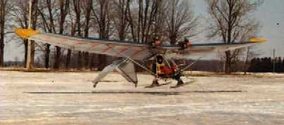


Excellent Lazair Ultralight Websites
Lazair.com Lazair Forum Lazair Forum on Yahoo LAZAIRFORCE ulflyer News Letter Ultralightnews Smithsonian Freedom Airtec Bob Comperini Toronto Museum UltraFlight Spinners Fatal Accident Fiberglass Tips Dale Kramer 25Years Thirty Thousand Feet - Aviation Directory